


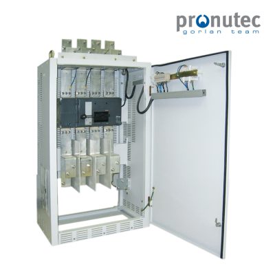
The heart of a low-voltage distribution panel: the incoming section
If a low-voltage distribution panel were a human body, the incoming supply would be its heart.
It is the point where energy enters the system, from which it is distributed to all outgoing feeders — just as blood flows from the heart to the rest of the body.

The most demanding area of the switchboard
The incoming section is also the area where the highest currents flow, making it one of the most demanding parts of the panel from a thermal, electrical and mechanical point of view. Just like the main arteries in the human body, any issue in this area directly affects the overall performance of the system. For this reason, its design must be particularly robust and properly dimensioned.
Connection reliability: a critical aspect
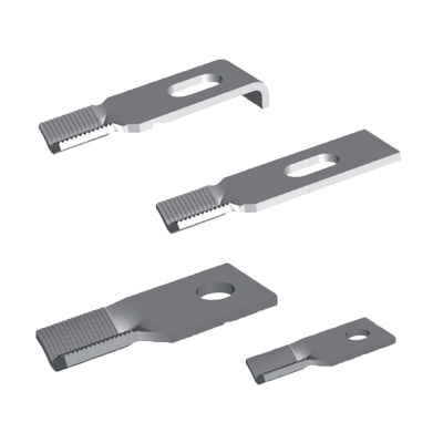
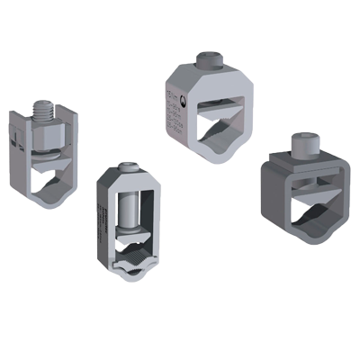
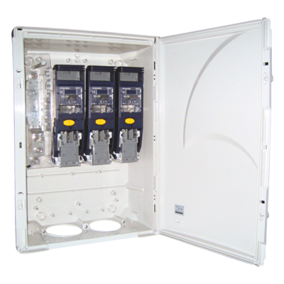
The connection of conductors at the incoming section must be suitable for the expected current and designed to ensure safe, ergonomic and long-term reliable installation.
This includes:
- Avoiding mechanical stress on terminals
- Ensuring correct tightening torque
- Minimizing contact resistance
Poor connections can lead to localized overheating and premature failures. Following the human body analogy, this area acts like a heart valve: if it does not function properly, the flow of energy is compromised and the system begins to degrade.
Designed for safety, ergonomics and real use
At Pronutec, special attention is paid to this aspect, as it is one of the areas with the highest level of interaction during installation and maintenance. Therefore, the design of the incoming section is not only approached from an electrical perspective, but also from ergonomics and operational safety, ensuring accessible, reliable and safe connections under all service conditions.
Insulation and safety
Clearances and creepage distances also play a key role in this area. An inadecute design may lead to internal discharges, tracking phenomena or even electric arcs.
These aspects are fundamental to ensure safe operation and compliance with applicable standards.
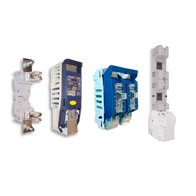
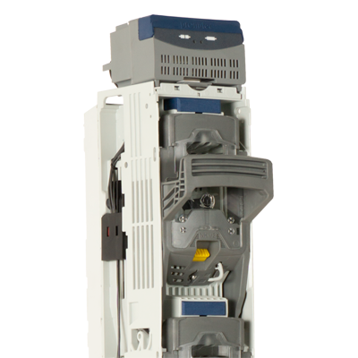
Equipment and configuration
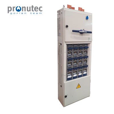
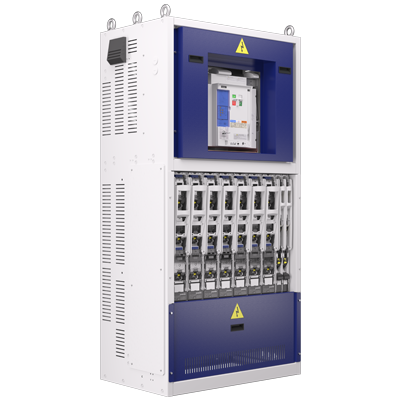
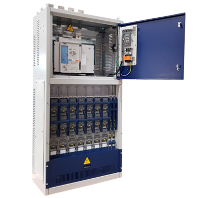
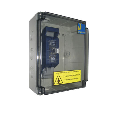
The incoming section can be equipped with different types of devices, depending on the required level of protection and switching functionality. This choice is key, as it defines the overall architecture of the panel.
Configurations may range from:
- simple solutions without main switching, directly connecting the transformer to the busbar
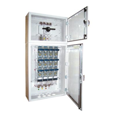
- to panels with incoming isolation
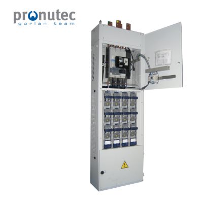
- to solutions with load break switches
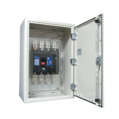
- or full protection using circuit breakers (MCCB or ACB)
Each configuration responds to specific application requirements and operating conditions.
Mechanical stresses under short-circuit conditions
The incoming section must also be designed to withstand mechanical stresses caused by short-circuit conditions.
Peak currents generate significant electrodynamic forces that can deform conductors or reduce insulation distances if not properly considered in the design. Just like the human heart must withstand peak stress conditions, this part of the panel must maintain its integrity even under extreme scenarios.
Conclusion
The incoming supply is the heart of the system because it is responsible for delivering energy and keeping everything in operation.
Its design is not only a matter of compliance, but a key factor in ensuring safety, reliability and continuity of service.
Because, just like in the human body, ……when the heart fails, no part of the system can function properly
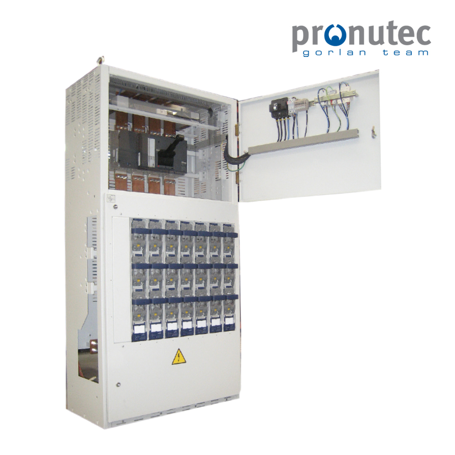
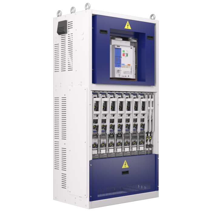
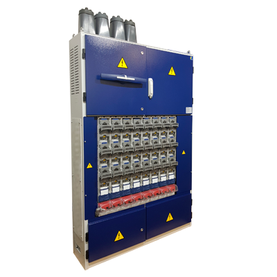
Pronutec solutions: incoming section design and configuration
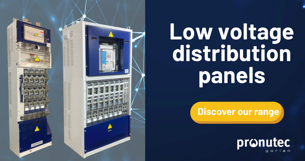
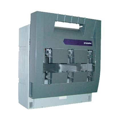
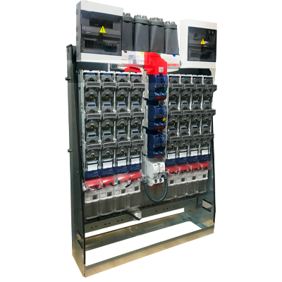
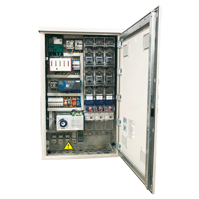
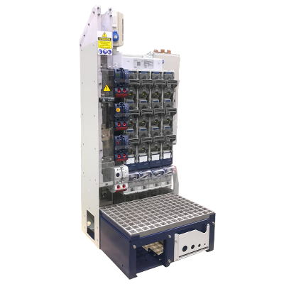
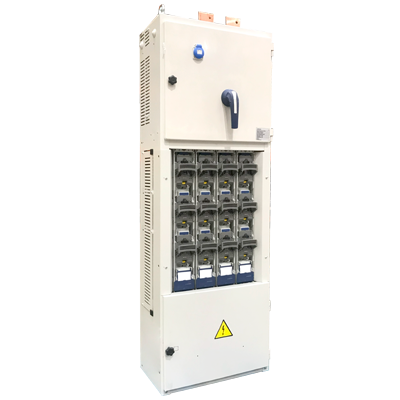
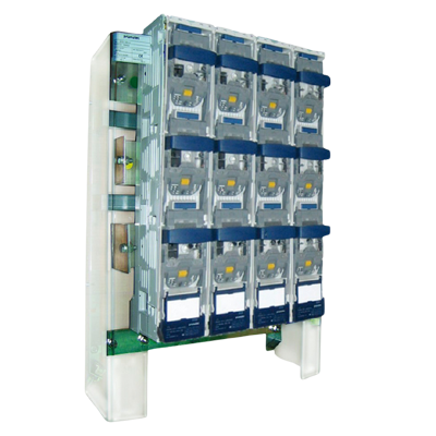
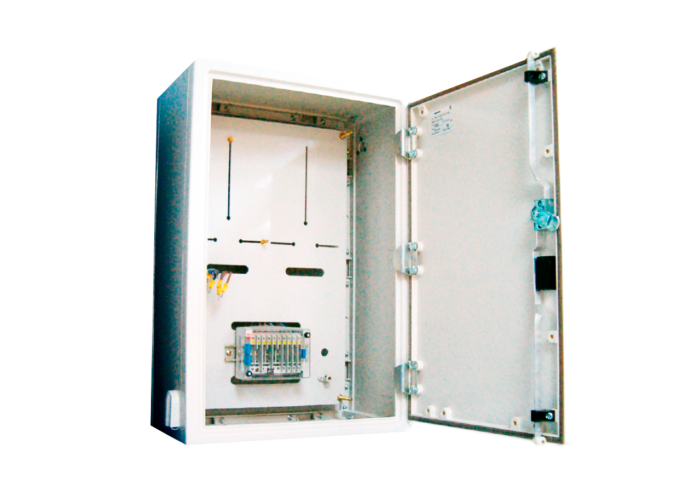
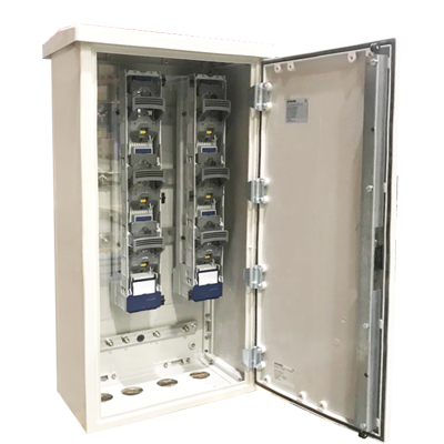
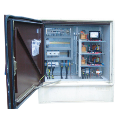
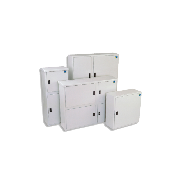
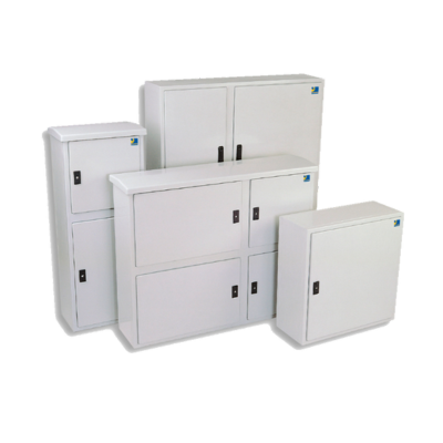
Pronutec offers a range of low-voltage distribution panels from 400 A up to 4000 A, with multiple incoming configuration options.
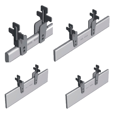
In each case, the incoming section is carefully designed to match real installation requirements, ensuring:
- proper connection capability
- correct distribution of electrical and mechanical stresses
- optimal integration with the busbar system and associated devices
This approach ensures reliable performance under both normal operating conditions and fault scenarios such as overloads or short circuits.
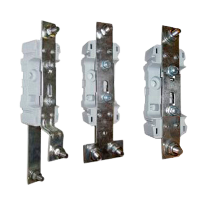
Incoming cable configurations
| Type of incoming connection | Description |
|---|---|
| Top entry | Cable entry from the top |
| Bottom entry | Cable entry from the bottom |
| Rear connection | Direct connection from the rear |
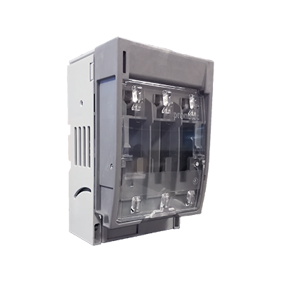
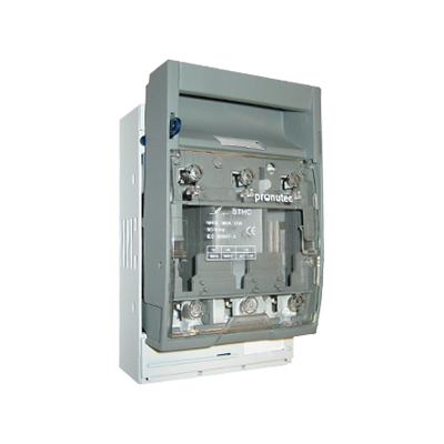
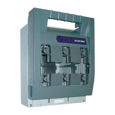
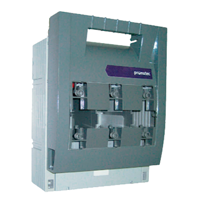
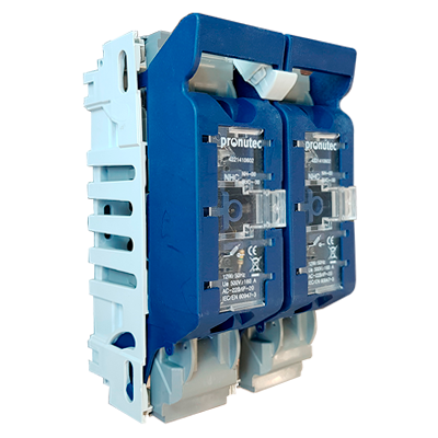
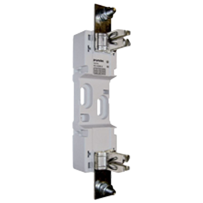
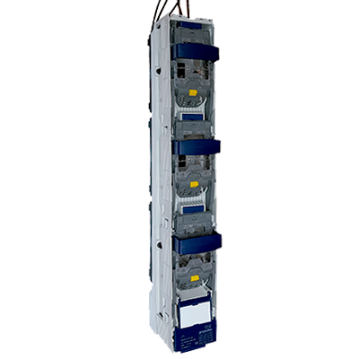
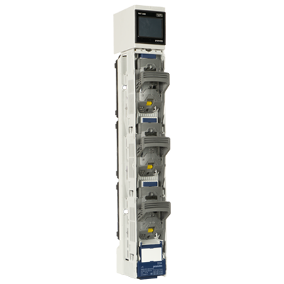
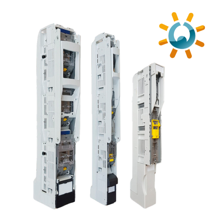
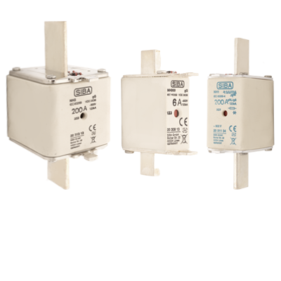
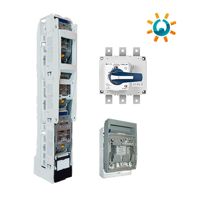
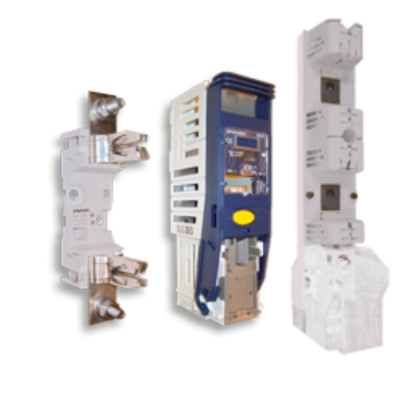
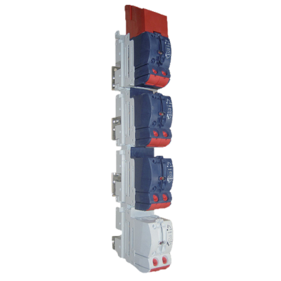
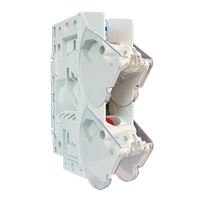
Available switching and protection devices
| Device type | Function |
|---|---|
| Switch disconnector | Isolation |
| Load break switch | Switching under load and isolation |
| Circuit breakers | Protection and switching |
| Fuse switch units | Protection and switching |
Typical incoming sizing (reference values)
| Transformer rating (kVA) | Icc (kA) | Panel rated current (A) | Typical cable configuration |
|---|---|---|---|
| 250 kVA | 10 | ~400 A | 1 x 240 mm² |
| 400 kVA | 15 | ~600 A | 1 x 300 mm² |
| 630 kVA | 20 | ~1000 A | 2 x 300 mm² |
| 800 kVA | 20 | ~1250 A | 4 x 240 mm² |
| 1000 kVA | 25 | ~1600 A | 4 x 240 mm² |
| 1250 kVA | 30 | ~2000 A | 6 x 240 mm² |
| 1600 kVA | 40 | ~2500 A | 4 x 300 mm² / 6 x 240 mm² |
| 2000 kVA | 50 | ~3000 A | 8 x 240 mm² |
| 2500 kVA | 60 | ~4000 A | 8 x 300 mm² |
Notes:
Values shown are indicative and may vary depending on installation conditions, operating voltage and cable characteristics.
The final configuration depends on conductor material, cable type, installation method and project-specific requirements. Final design verification shall be carried out in accordance with IEC 61439.
Esther Plasencia
Head of R&D at Pronutec
Related News
Low Voltage Panel. A Key Element in Electrical Infrastructure
LV panels play a crucial role in managing and protecting the electrical supply in residential,...


Pronutec, a ![]() company
company
