


The Circulatory System of a Low-Voltage Distribution Panel: The Busbar System
If in a low-voltage distribution panel the incoming section is the heart, the busbar system is its circulatory system.
It is responsible for transporting energy from the incoming supply to each of the outgoing feeders, distributing it efficiently throughout the assembly — just as blood flows through arteries and veins to supply every organ in the body.

The busbar system constitutes the internal “network” of the panel. Through it, current is distributed to the different functional units, protection devices and outgoing circuits. Its design directly determines the electrical performance of the assembly, both under normal operating conditions and during fault situations.
Just as not all arteries in the human body have the same size, in a distribution panel the busbar system is dimensioned according to the current it must carry. The main busbars act as large arteries, while the branches supplying each outgoing feeder are equivalent to smaller vessels.
Current, temperature and efficiency
One of the key aspects of a busbar system is its ability to carry current without generating excessive heating.
The cross-section of the bars, their arrangement and ventilation conditions determine the temperature rise of the assembly — a critical factor in design verification according to IEC 61439.
The cross-sectional area must be adequate for the expected current, ensuring proper heat dissipation and preventing overheating. It is not only a matter of meeting nominal values, but of ensuring reliable performance under real operating conditions, including temporary overloads and fault scenarios.
DIN 43671 provides a useful reference for busbar sizing, incorporating correction factors to account for actual operating conditions.
An improperly dimensioned busbar system is comparable to a circulatory system with obstructions: resistance increases, hot spots appear, and overall efficiency and reliability are reduced.
Short-circuit withstand capability
In addition to thermal performance, the busbar system and its supporting structure must be capable of withstanding the electrodynamic forces generated during short-circuit conditions.
These forces can be extremely high and may lead to deformation of the conductors or reduction of phase-to-phase distances. In human terms, this can be compared to a sudden spike in blood pressure: if the circulatory system is not prepared, failure may occur.
The physical arrangement of the busbar system is another key factor. Phase-to-phase distances, clearances to earth, and the correct definition of creepage distances and insulation paths ensure that internal discharges do not occur.
Therefore, busbar design is not based solely on rated current, but also on the proper design of fixing points and supports to ensure the ability to withstand short-time withstand current (Icw) and to maintain required insulation distances.
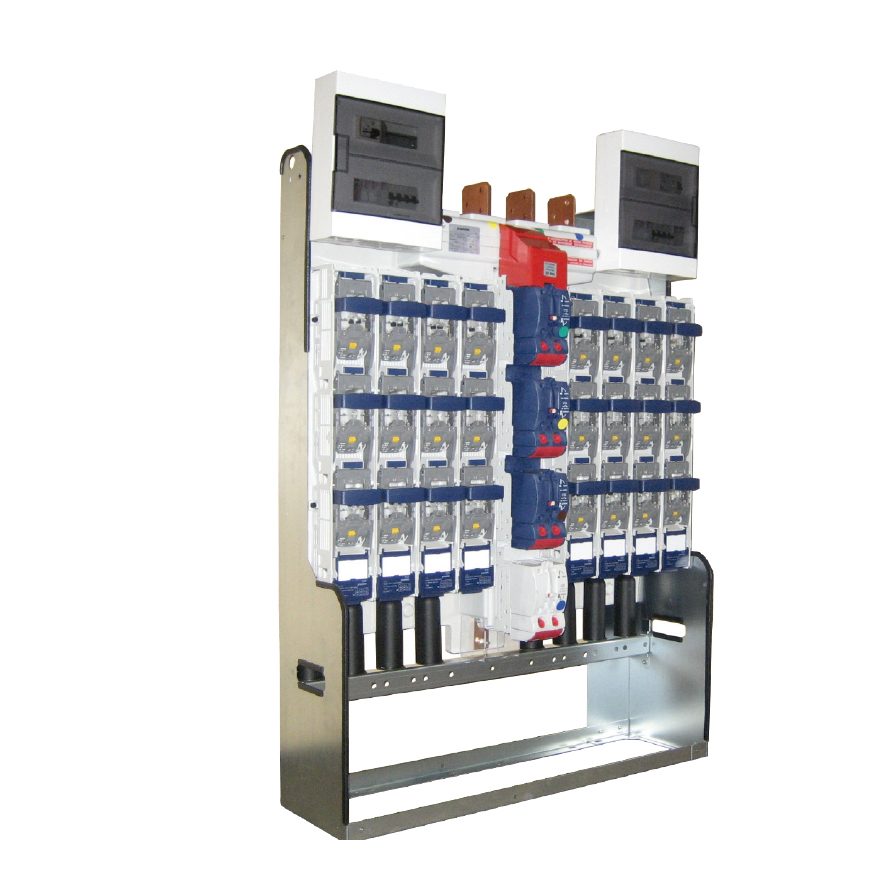
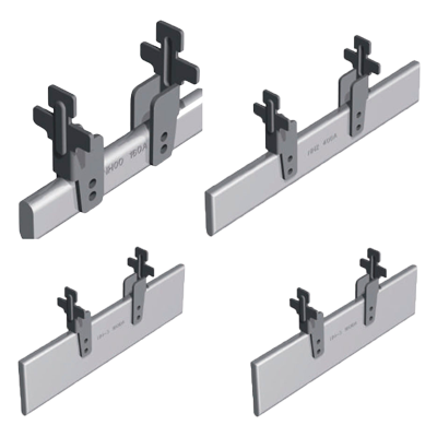
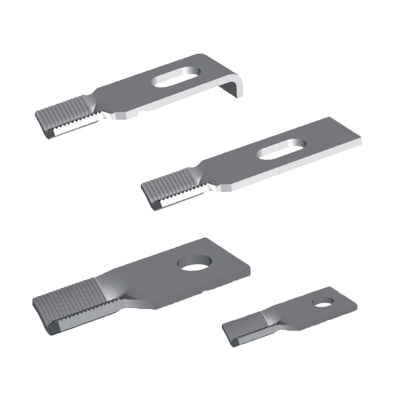
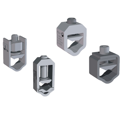
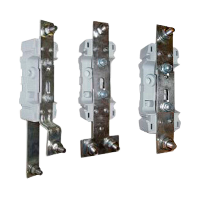
Connections: the critical points of the system
In practice, many issues do not arise in the busbars themselves, but in their connections. Busbar connections must ensure:
- low electrical resistance
- good surface contact
- adequate mechanical pressure
A poor connection generates localized heating, which can lead to material degradation or system failure. This is equivalent to a restriction in blood flow or an obstruction in an artery.
At Pronutec, special attention is paid to the geometry of the busbar system, the quality of connections and proper heat dissipation, ensuring a robust, safe and durable system.
This approach goes beyond design. During the manufacturing process, tightening torques of all connections are carefully controlled, ensuring proper contact pressure and preventing high contact resistance that could lead to hot spots or premature failures.
This control is essential, as many real-world issues arise not in the conductors themselves, but in their connections. For this reason, at Pronutec this aspect is treated as a critical quality factor, ensuring stable and reliable electrical performance throughout the lifetime of the panel.
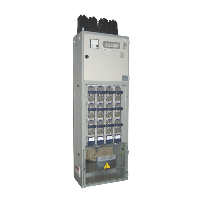
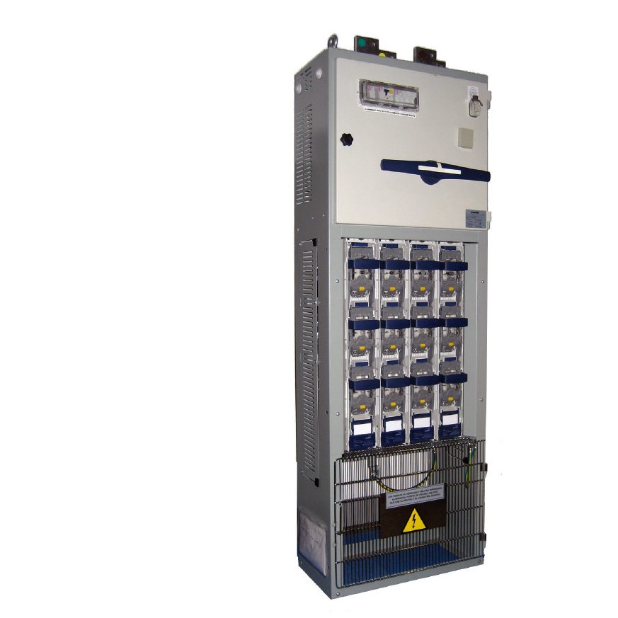
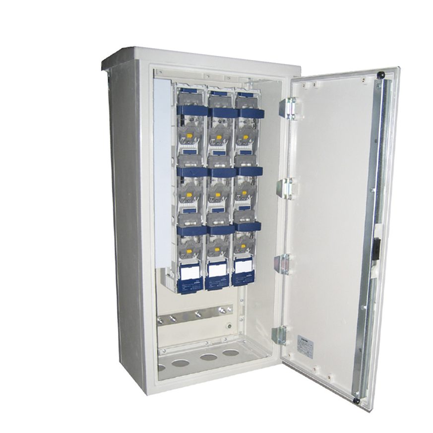
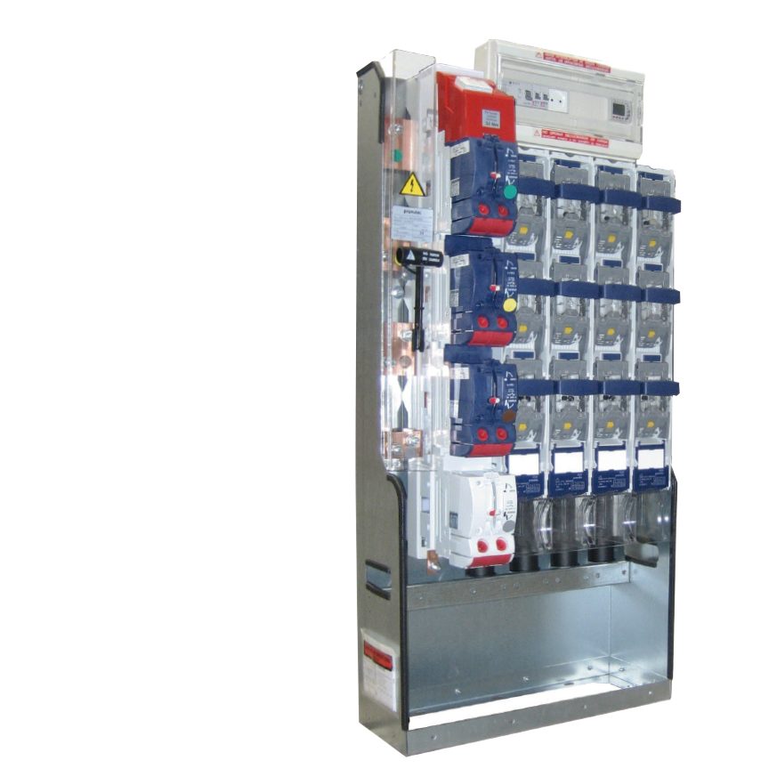
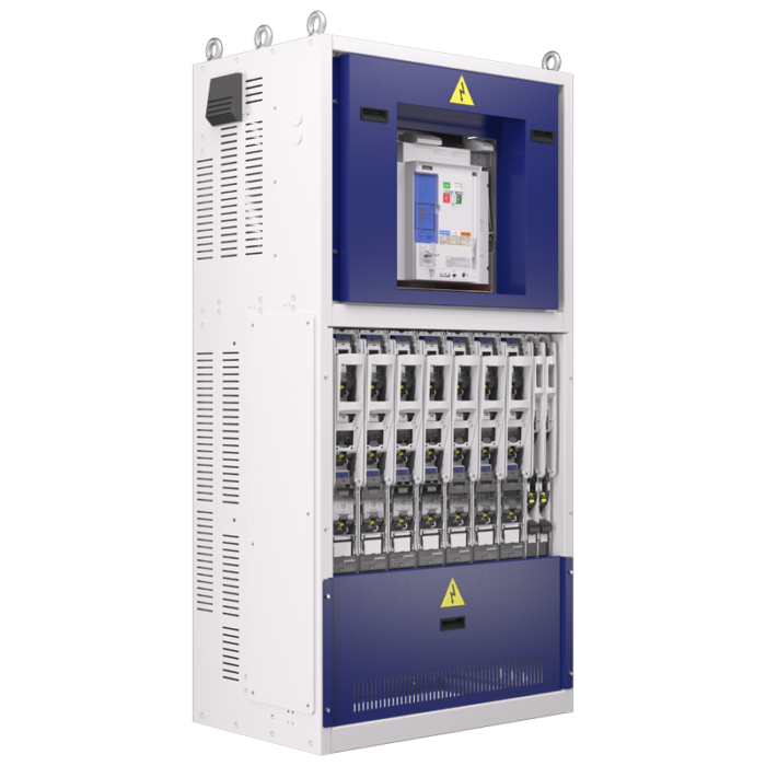
Pronutec solutions: busbar system design and configuration
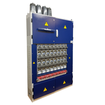
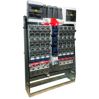
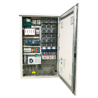
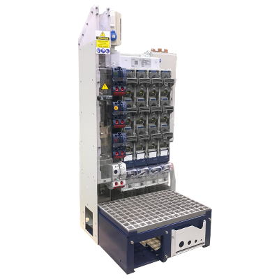
This design approach is directly reflected in the busbar solutions implemented across the Pronutec range of low-voltage distribution panels.
The busbar system is treated as a key element of the overall performance of the panel. Each configuration is adapted to the rated current of the system, from 400 A up to 4000 A, ensuring efficient energy distribution and reliable performance under both normal operating conditions and short-circuit conditions.
Typical configurations used in our low-voltage panels are shown below:
Available current ranges
| LV Panel rated current | Typical busbar configuration |
| ~400 A | 60 x 5 mm |
| ~600 A | 40 x 10 mm |
| ~1000 A | 50 x 10 mm |
| ~1250 A | 60 x 10 mm |
| ~1600 A | 80 x 10 mm |
| ~2000 A | 100 x 10 mm |
| ~2500 A | 2 x (100 x 10 mm) |
| ~3200 A | 2 x (120 x 10 mm) |
| ~4000 A | 2 x (160 x 10 mm) |
The values indicated are for reference only and may vary depending on installation conditions, ventilation and operating environment.Final design verification shall be carried out in accordance with IEC 61439.
Conclusion
Because, just like in the human body, an efficient circulatory system is essential to ensure the proper functioning of the entire organism
Esther Plasencia
Head of R&D at Pronutec


Related News

Photovoltaic in AC Grids – Switchgear and Combiner Panels
Con el desarrollo y lanzamiento de los nuevos inversores de string, las plantas e instalaciones...

Low Voltage Panel. A Key Element in Electrical Infrastructure
LV panels play a crucial role in managing and protecting the electrical supply in residential,...
The heart of a low-voltage distribution panel: the incoming section
If a low-voltage distribution panel were a human body, the incoming supply would be its...


Pronutec, a ![]() company
company
